Tuesday 29 November 2011

Elevator

To create the elevator I made a simple L shape with two boxes and then used the swift tool to split the polygons and extrude new shapes. I did this to create the box shape for the lift but maintaining two sided faces. After I got the basic shape i then went on to create a separate cone shape and use it, with the ProBoolean tool to create light wholes in the roof. The last stage of creation was the handling rail around the elevator. This was made using a cylinder which was then extruded and rotated to create a long bend.


First basic shape

Using symmetry to mirror the first half


Elevator with hand rail


After I had created the model I then used the symmetry tool to duplicate the other side, saving myself half time and work. To save more time when coming to animate I also made a Morpher version of the elevator with the doors closed, so that now the elevator could be easily animated into opening and shutting.

Elevator using Morpher

Swift Loop - (Learning A The Technique)

A new tool I learnt to use was the swift loop tool. This allows the user to create a new set of faces by selecting a line to split the original. The first step to doing this is to convert the shape into an editable poly.

To find the tool you can then move to the toolbar in the top left hand corner named, "graphic modelling tools" and then going to the "edit" sub-bar. This drops down into a new menu and the tool can be found in the right hand corner. You then loop the item and then create new vertex where necessary, creating new ploys.

This works well when changing whole shapes is required and the user wants to have a good flow of polys.


Selecting the Swift Loop tool

Using the tool to create new vertex

The finished ajustment to the poly

Friday 25 November 2011

Display Cabinet

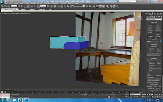
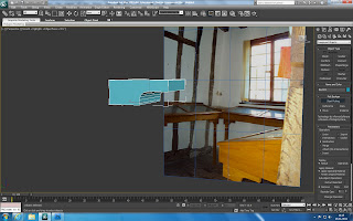
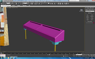
To design the display cabinet I started with the legs. To do this I used the Pro Boolean tool. The way this works is by first creating two shapes. First the shape you want to cut into, and secondly the shape your going to use to cut the shape.
Both objects

The next step is to move the second object into the 1st, covering the section you want to cut into. Then by selecting the first object and going onto the compound shape tab you can select the Pro Boolean tool.
Objects n overlapping

After selecting Pro Boolean, the next step is to select the "Start picking" option and then select the second object (the cutting tool). This will then cut the shape into the first object.

Finished object
 This helped to create the wooden corners of the display table. The next step was to add a long cylinder to create the basic leg shape. Once this was done I moved on to create the basic shape for the display cabinet and added the lefs to the bottom.
  
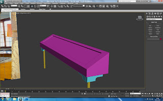
Display cabinet outer case
To create this outa case I made a box shape, moved the vertexs to create the triangular shape and then used the inset and extrude tool to create the inside space. The next step was to create an inner layer that will be used to mimic the glass case.

Glass layer

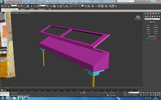
The final step was to create the wooden top finish to go over the top of the glass case. This was done by making a copy of the box, cutting the top layer off and then extruding it out to give it depth. I then used the chamfer tool to round the edges and fit it to the display cabinet.

Display cabinet lid

Finished cabinet

Gravestones and Display Cabinet

After creating the map plane I went on to create two variations of gravestone to go into the surrounding area, as well as the display cabinet that can be found in a room on the bottom floor of the guild.

To create the first gravestone I used a box to make the outline shape and then used the shamfer tool to curve the top two corners. This gives a good representation of a standard gravestone. I then textured it with a simple gravestone gray texture, as this model will not be seen in detail or for very long.

Gravestone 1
The second gravestone was made by creating a simple box on the ground and then using the inset and extrude tools. I used the inset tool to make a face for a slightly smaller box, and then extruded it out from the larger base one. I then continued this step until I had the disiered shape of a block bottom with a cross on the top.

Gravestone 2
The creation of the Display Cabinet will be covered in the next post.

Adding The Surrounding Area

Among other things I started to design the outside and surrounding area of the guild. I made this more easy by using google maps to find a birds eye view of the guild and place it onto a plane. I then used bitmap fit to scale it correctly and then rotated it until the guild was facing the right direction.

I then started to design basic shapes and continued the road out to start giving the surrounding area some depth. As the project continues I will continue to add buildings and detail to the area. This is important as the animation will show the guild and area from the outside.

The map on the Plane

Monday 14 November 2011

Other Rayfire Animations

A few other earlier animations made using the Rayfire plug-in.

Photo"Shot".

Earth.

Rayfire plug-in For Max Studio's (Learning A The Technique)

Over the past week I have been spending time working with the Rayfire plug-in tool for 3D Studio Max. This plug-in allows the user to create highly detailed explosions, destructive models and other such effects that can be used for destructive purposes. As a group we decided that we might be able to use something from this package to help animate the building model. I decided to follow up on this and learn some ways in which we could possibly have the walls of the building crumble. The key advantage to this feature is that it heavily reduces the amount of work needed to be done to create such effects, as well as having its own engine to create the animation.

To begin with you create a model as usual, for this example I created a simple garage/shed building with 3 box's as sides and 2 to make the roof. After which the next step is to open then Rayfire toolbar by selecting create object and opening the drop down box and going to "Rayfire Tool".


Basic Model.

RayFire Tool bar.
Once the tool bar is open the next step is setting the objects as impact objects, unyielding objects, bombs or shooters. In this example the model will be placed as an impact objects via simply clicking add, whilst being selected in the simulation tab, and the floor plane will be set as unyielding in the physics tab, to give the model a base. Making the floor unyielding makes the object a floor for the model to fall onto without being effected by the same animation effects. As a reference the bomb tool is very effective, allowing you to use a pointer to create a blast area and creating slices in the object according to the bombs location.

Adding impact objects.

Adding unyielding objects.

After adding both sets of objects the fun starts and the user can move onto the Ray/Xplosion tab and play with the different settings. These vary from different slice techniques, slice iterations, noise and chaos. Different slice techniques allow the user to create different destructive patterns via changing the point of origin. For example bomb as mentioned before uses a point and creates slices around it, and more iterations nearer the bomb point. However creating this I used the irregular fragmentation type, meaning that instead of creating the slices around a point, it creates slices randomly with no correlation between size and length. Number of iterations is how many slices are to be used, and noise and chaos effect how bumpy and pointing each of the separated objects will be, 0 giving straight edges and 1+ giving increasingly bumpier edges.

Fragmentation selection.

The objects fragmented, ready to be animated.

After the fragmentation program has created all of the slices for the objects the final step is to allow Rayfire to animate the destruction. This is done by going onto the physics tab in the Rayfire toolbar and setting the start frame etc, and clicking on the play button. This then sets key frames along the time line and creates a stand alone animation ready for rendering.

Animation bar.

The final animation.

After looking at the plug-in for several hours I've found I have got quiet good at the tool. It has a lot of different animation tools which are easy to use and quick to run. I have found myself creating a few little animations recently that have taken less then 5 minutes to create. The next step is to continue learning and playing with colliding and moving objects to give the fragments more movement then just gravity.

After looking at the tool I have however come to the conclusion that the tool is to "messy" for our walls in our group animation, but could possible be used on the buildings surrounding area, as a way of singling out the building for the main animation. 


Thursday 10 November 2011

Support Beams

To create the support beams I made one basic rectangle and then positioned two of them together as the main support beam . This gave me the starting point for positioning the rest of the beams. I continued by placing seperate beams at either ends of the centre beam and then joined them together with five more beams to create a mesh pattern. 


Support Beams.


After this I then continued to put in the last beam, and corner brink work which linked onto the stairs and the damaged area. 

Final Beams.

Stairs and Railing

To create the stairs I simply created a block, and sized it to fit the pathway. I then created two clones of the block and moved them out, aligning them with there 1st block to create the stairs. After this I then went back to the first block and resized it to account for the damage. This damage will be added in later into the gap shown in the image below.

Front Stairs.
To make the stairs look authentic I made the last step slightly bigger then the other two, so that when the road began to curve, it would continue to fill the gaps between the building and the road.


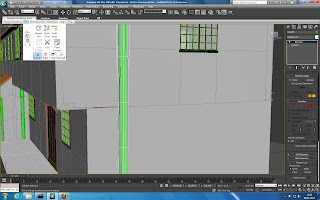
The next step was to create the railing on the side of the steps. This was done by creating two rectangular shapes, along with two cylinders. These were all then placed together using the vertex snap tool, and moved to align with the stairs. The final thing to do was to bevel and extrude the top of the railing to give it a finished look.


.
Front Railing