Working on the Head Model
Overall I found the head model very challenging and uncomfortable, although it showed me a lot of new techniques. Honestly the biggest issue I had with the model was trying to work on my own face. I have always found it difficult to model/draw organic models as well as having a dislike for drawing self-portraits. With that said I did learn a lot of new techniques and enjoyed the time I spent creating the face.
Looking at the model I find it hard to see myself. The parts I dislike the most are the chin, cheek bones and neck. I think that the chin is far to pointy to be mine, and the cheek bones need to come out more, giving the model a more rounded cheek. The neck is only a small issue but I found that it came out to wide and had a few unknown bumps in it.
The parts of it I like are the nose, eyes and hair. The nose is still a little too straight but it looks to be the same size and have the same bridge. The eyes are the same size and I feel they are the right distance from the nose. The eyes still need work done on them and detail added but the basic figure is there. The hair also seems to follow the right mold, showing similarities to the real hair style and size. The only issue I have with the hair is the white light highlights it seems to show.
To conclude, I feel that I have created a low quality head model, with some likenesses to my own head. If I where to repeat the model I would defiantly spend more time on the models shape before textures where applied, as this caused a big issue when trying to adjust it later. One last thing I would do is add a second and third hair and fur modifier to the model and create realistic looking eyebrows instead of the textures ones that can be seen in the final render.
Working on the Guildhall
I found this part of the module the most interesting, fun and educational. I found that during the time I spent developing the models and the animation I learnt several good techniques as well as tips including;
The slice tool
The pro Boolean tool
How to use Rayfire
How to use lighting effectively and the specifications
How to use textures more effectively and give them properties
How to animate with multiple tools and camera paths
How to use the network render (Backburner) for Autodesk
Learning all of these skills and more has greatly increased the speed at which I can work as well as the quality of the final product. The only two things I would have to mention negatively with this project was the time restriction and the lack of equipment. When we started the project we were given six weeks to complete all of the models as well as the animation. This was difficult to keep to and we ended up taking another week to finish off the animation. I felt that to complete the high quality models we should have been given six weeks alone, with another six weeks for animation, rendering and video production. The other problem we had was the lack of equipment, broken computers, nowhere to render most of the time and no computers that could work with Rayfire. This caused constant problems throughout the project, but is respectably unavoidable.
The rest of the group seemed to work well with odd moments of weakness, but as a regular group member I can understand that stress levels and issues can cause arguments at any time and the best thing to do is relax and come back to the discussion later. I feel that we all worked hard and well, notably Jack Cassie who did a good job leading the team and working hard to learn the plug-in Rayfire with me and create the animations. The group and I worked hard to complete all of the models, animate the finalise the final product, and I could ask for no better.
The things I would do next time would firstly be to try and use a better range of computers, that give all of us access to Rayfire as apposed to just me and Jack. I would also like to have worked more on the lighting, as this was a big issue. We originally had two renders of the product, one with global illumination and one using the daylight system. The problem we had was that the global illumination copy looked unreal, but the daylight copy had to many beams of light, giving a realistic lighting effect but smudging the walls and creating white light in points where there shouldn't have been. Me and Jack both spent around twelve hours over the period of two days trying to create a better lighting environment with no success. This would have made the HD renders look more impressive and realistic.
In all I felt that the group worked extremely hard and I personally learnt a lot, as well as gaining the motivation to learn even more. In my opinion the project still looks amazing and one of the highlights of my educational lifetime. It could in respect use some work in places and alterations to the lighting, however given enough time anything can be improved and with that in mind, it's finished
Module Evaluation
Wednesday 21 December 2011
Tuesday 20 December 2011
Using Morpher To Animate
To demonstrate my skills I wanted to use the morpher modifier to animate my model in some form or another. To do this I first had to turn off the hair and fur modifier as this always wanted to take the priority slot and I could not find a way to animate it with the hair still on the model.
After the minor set back I then went on to create a very simplistic animation whereby the eyes move from side to side. This was done purely to show I have the ability to use morpher and animate models and to save time by not doing a more complex movement. To do this I made two copies of the original and then rotated the eyes. The important thing when using morpher is to not add or remove any vertex or polygons, as the morpher will only work as long as the only change that can be made is the positions of the vertex/polygons.
The final animation I created can be seen below.
 |
| The head and morphers |
After the minor set back I then went on to create a very simplistic animation whereby the eyes move from side to side. This was done purely to show I have the ability to use morpher and animate models and to save time by not doing a more complex movement. To do this I made two copies of the original and then rotated the eyes. The important thing when using morpher is to not add or remove any vertex or polygons, as the morpher will only work as long as the only change that can be made is the positions of the vertex/polygons.
 |
| Morpher looking right |
 |
| Morpher looking left |
Finishing the Head
With the project time coming to an end I had to decide to show i had the ability to use other tools in the program instead of creating detail on the model. For this reason I finished the model's texture and the ears and began to add hair using the "Hair and Fur" modifier. The head itself looked unlike myself and had several issues, most notably being that the ear textures did not match the head, as well as the texture containing hair. If I where to re-create the texture I would make the entire head skin colour, and then only using the modifier to add hair.
The hair tool is surprisingly difficult to use, as I had many problems cutting the wrong parts of the hair off, and moving it in the wrong direction. After working on it for some time however I managed to create hair that could resemble mine, in respect to the length and basic shape. The one down side I had was the hair seemed to give off a white light. This may have been a highlights problem with the render, but without more time it is difficult to say for sure.
 |
| Finished texture map |
 |
| Ear texture attachment |
The hair tool is surprisingly difficult to use, as I had many problems cutting the wrong parts of the hair off, and moving it in the wrong direction. After working on it for some time however I managed to create hair that could resemble mine, in respect to the length and basic shape. The one down side I had was the hair seemed to give off a white light. This may have been a highlights problem with the render, but without more time it is difficult to say for sure.
 | ||
| Using the hair modifier |
 |
| Changing the hair colour |
 |
| Render of Hair |
The Final Steps
The last few days me and the group have been spending time rendering both the scenes and then the frames again inside Adobe Pro (The video editing software were using for this presentation). As we did this I continued about re-rendering some of the scenes again with different lighting specifications to improve the quality.
As I did both of these things I also used my time to create the credits scene for the final presentation, as well as showing the others in my group how to put text overlays onto the moving images. These make our presentation look more professional and gives it a modern feel.
Monday 19 December 2011
Network Render
To render the scenes effectively we decided to look into network rendering. This was so that we could have high quality renders, but not have render times that go into double digits. The main idea behind this is simply having all of the textures and models needed on one master computer and then having others linked to it via server (using there IP addresses).
This allowed us to render full scenes in 30 minutes that would have taken 3-4 hours on a single computer. The way the master computer works is by allocating each slave computer an image to render, and then assigning it a new one after it finishes. With this process being repeated on 30 - 40 computers, its understandable how effectively this can work. The bonus to this is that if one of the renders crashes, the image it was given gets re-allocated and sent to the next slave.
This allowed us to render full scenes in 30 minutes that would have taken 3-4 hours on a single computer. The way the master computer works is by allocating each slave computer an image to render, and then assigning it a new one after it finishes. With this process being repeated on 30 - 40 computers, its understandable how effectively this can work. The bonus to this is that if one of the renders crashes, the image it was given gets re-allocated and sent to the next slave.
Animating
After all of the models and textures where finished we moved onto animating the scenes. The main task I had in animating was creating the camera angles for the HD shots, including there path constraints. I also learnt how to effectively light the scenes with the daylight tool from Jack Cassie, and in return started him off with the basic commands in Rayfire. (The Rayfire animations where given to Jack to complete as unfortunately the program requires high-spec computers, of which only he owns).
The way I completed the camera movements was mostly done using splines and path constraints. To do this you simply draw out the path you with the camera to follow, and then apply the camera to said path. The camera will then go from start to end of the path, allowing the user to use AutoFrame to focus of the camera shot when necessary.
The lighting was created using the daylight system, where by you use a beacon to indicate the sun, and then "portals" that you can places inside of windows and doors to allow light through. This helps create realistic shadows and lighting. The only issue with this is that as a group we found the images would look grainy, and there would be clear points where the light beams could be seen, ending on walls. This made some points in the images overly bright with dots, and then making darker areas such as walls look very dirty and blotchy. For example in the image below there are a few spots, notably the computer and celling where the light spots can be seen. The blotches can be seen on the wall surrounding the window and again further down the wall.
The scenes I animated where:
Library
Shop
Museum
Guild Room
The way I completed the camera movements was mostly done using splines and path constraints. To do this you simply draw out the path you with the camera to follow, and then apply the camera to said path. The camera will then go from start to end of the path, allowing the user to use AutoFrame to focus of the camera shot when necessary.
 |
| Path constraints and camera |
 |
| Daylight system used with "portals" (Placed lower then usual) |
The lighting was created using the daylight system, where by you use a beacon to indicate the sun, and then "portals" that you can places inside of windows and doors to allow light through. This helps create realistic shadows and lighting. The only issue with this is that as a group we found the images would look grainy, and there would be clear points where the light beams could be seen, ending on walls. This made some points in the images overly bright with dots, and then making darker areas such as walls look very dirty and blotchy. For example in the image below there are a few spots, notably the computer and celling where the light spots can be seen. The blotches can be seen on the wall surrounding the window and again further down the wall.
 |
| Library Render |
The scenes I animated where:
Library
Shop
Museum
Guild Room
Wednesday 14 December 2011
Rayfire Work
Now that I have had a few days to work singly on modelling and animation I have begun developing my skills using the Rayfire tool. To do this I started following a tutorial online (Link Below) which starts with you creating a grenade. Doing this took around an hour and not only showed me new techniques but taught me very simplistic ways to in harness the quality or a render with lighting and shading.
Tutorial Link: http://cg.tutsplus.com/tutorials/autodesk-3d-studio-max/3d_cg_vfx_autodesk_3dsmax_rayfire_break_glass_dynamics_glow_ball/
Tutorial Link: http://cg.tutsplus.com/tutorials/autodesk-3d-studio-max/3d_cg_vfx_autodesk_3dsmax_rayfire_break_glass_dynamics_glow_ball/
 |
| Studios before added shading |
 |
| Render before added shading |
 |
| Studios after added shading |
 |
| Render after added shading |
Tuesday 13 December 2011
Populating Rooms
Today I went about populating the ground floors rooms, adding in the models we had built as a group in the past few weeks. This included heavy work on the library, museum and shop, adding models and textures. The main problem I found were resizing some items, notably the bookcases and books. To avoid this issue I used the originally sized models and then added more shelves to them.
One new model I created was the postcard Rack, which I made to give the shop a more detailed appearance. This was made using blocks to create the shelving unit, and then used thin boxes piled together to give the appearance of postcards. After creating these i then desired to texture them with local images of Finchingfield, as well as the design team behind the animation/model (Us).
 |
| Museum Room 1 |
 |
| Shop Room |
 |
| Library Room |
One new model I created was the postcard Rack, which I made to give the shop a more detailed appearance. This was made using blocks to create the shelving unit, and then used thin boxes piled together to give the appearance of postcards. After creating these i then desired to texture them with local images of Finchingfield, as well as the design team behind the animation/model (Us).
 |
| Postcard Rack |
Monday 12 December 2011
New Additions to Group Work
Over the past week I have created too extensions to the group work project. The first change was to the elevator, which involved a complete re-design as the original was model on a more universal elevator as opposed to the intended disabled platform. The new platform now acts as a moving platform rather then a lift, meaning that no support beams or pulley systems are needed to lift the platform. The doors are now glass and swing open rather then open as conventional lift doors open. Both doors are fitted with a door open button, as well as a lift call button.
The second addition to the project was the new stairs. These have been straightened out, re sized and had the walls around them built out. At this moment in time it is difficult to tell whether there are railing's either side or not but they may be placed into the project later.
 | |||
| New disabled lift |
 |
| New stairs for the new building |
Monday 5 December 2011
Head So Far
I have been working hard on the head the past few weeks and I am now at the stage where my texture requires some detail. I fully created the texture and then decided to re-created the mouth after blurring it with the liquidation tool to much.
After finishing the second texture I noticed that my model had a slit in the nose and some small areas in the head that had become un-wielded. To this point I have tried altering the model but have been effecting the UVMap to much. I have recently learnt however that by collapsing the layers of the model into each other it is possible to modify the model without effecting the texture. I will be tring this in the next few hours.
 |
| First generation of the texture |
 |
| Second generation of the texture |
 |
| Second generation texture applied to head model |
After finishing the second texture I noticed that my model had a slit in the nose and some small areas in the head that had become un-wielded. To this point I have tried altering the model but have been effecting the UVMap to much. I have recently learnt however that by collapsing the layers of the model into each other it is possible to modify the model without effecting the texture. I will be tring this in the next few hours.
 |
| Nose error |
Texturing The Head
To texture the hair I first saved the UVMap image made in the previous blog and opening it inside of Photoshop. This gave me a clear layout of the shape, the texture would have to fill. The first step was to save the image as a Photoshop file and then apply it as a texture inside Max Studio's on my face, giving the face the outline texture. To create the face image I used patches of skin from the image I used as the guide to creating the face model.
I did this by using the lasso tool to select parts of the skin from the old image and then duplicating them on the texture file. I then scaled and placed them appropriately using the warp and blend tool.
The warp tool splits the selected object into a small number of separate areas, and allows the user to stretch and free form the image.
Once the shapes are image sections are in place, I then merged the layers (excluding the background and guide) and used the blend tool to create an texture that appeared to flow better. The blend tool works by selecting an area you wish to make flow into another, and using a sample of the second material's area creates a blend of the too.
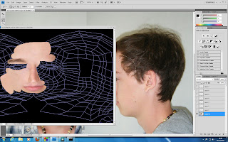 |
| The main creation of the texture |
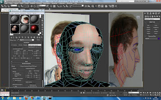 |
| The texture view in Max Studio |
I did this by using the lasso tool to select parts of the skin from the old image and then duplicating them on the texture file. I then scaled and placed them appropriately using the warp and blend tool.
The warp tool splits the selected object into a small number of separate areas, and allows the user to stretch and free form the image.
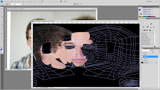 |
| The Warp Tool |
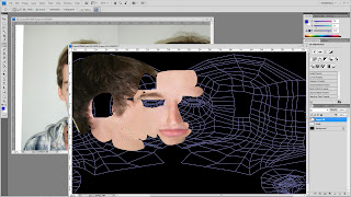 |
| Select the section you want to blend |
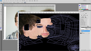 |
| Select the section you want to blend to |
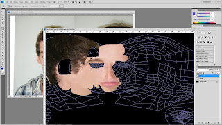 | |||
| The blend tool merges the too selections and forms a smooth blend |
Another tool I used, mostly for the lips and soon to be the eyes is the liquidation tool. This allows you to zoom into the image in great detail and use scaled brushes to manually move clumps of pixels around. This helped a lot in moving my lips up and away from my chin. The only draw back from using this tool is that moving to much can blur the image.
The mouth is too close to the chin and to thick round the edges
| The lips have been pushed up slightly and moved inwards |
Thursday 1 December 2011
UVMaping the Head
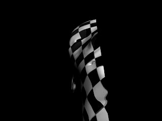
After creating my basic head shape I then went on to modify certain areas, including the cheek bones, nose and eyes to make them more in line with the reference images. The next step on from this was to start UV Mapping my model. This meant deselecting symmetry and selecting all of the poly's faces with the paint tool, ensuring to leave the ear and surrounding areas as these would be done separately. I then put the face model inside of a cylindrical map, ensuring that there was enough space for the mirror object to fit inside with it.
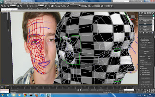
From this i then applied a checkered pattern to the whole model to see where the texture was stretched out. This was to help the task of moving the mapping around to assist in placing the material equally. Clicking on "Edit" inside the mapping parameters brought up the editor, which can be seen in the image below. This allowed me to use the relax tool to spread the material vertex's out. This changed the way the material would be laid out, without changing the vertex's of the model.
After the model was spaced out efficiently, and I had checked for high numbers of inverted and overlapping faces I resized and fit the model to the texture background.
After the face was completed I then moved on to reapeating these stages for the ear, this time making the mapping with a pelt map insted of a cylindrical shape. After completing both of these steps I feel reasonably pleased with the results. I an see there are still errors, mostly in the neck and top of the head, but due to time and other work Im going to pursever with what I have.
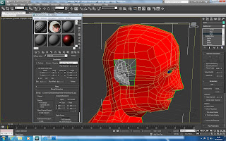 |
| Face highlighted |
From this i then applied a checkered pattern to the whole model to see where the texture was stretched out. This was to help the task of moving the mapping around to assist in placing the material equally. Clicking on "Edit" inside the mapping parameters brought up the editor, which can be seen in the image below. This allowed me to use the relax tool to spread the material vertex's out. This changed the way the material would be laid out, without changing the vertex's of the model.
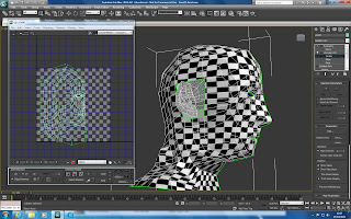 |
| Using the editor |
After the model was spaced out efficiently, and I had checked for high numbers of inverted and overlapping faces I resized and fit the model to the texture background.
 |
| Render after UV Mapping |
 |
| Ears UV Mapped |
Tuesday 29 November 2011
Elevator
To create the elevator I made a simple L shape with two boxes and then used the swift tool to split the polygons and extrude new shapes. I did this to create the box shape for the lift but maintaining two sided faces. After I got the basic shape i then went on to create a separate cone shape and use it, with the ProBoolean tool to create light wholes in the roof. The last stage of creation was the handling rail around the elevator. This was made using a cylinder which was then extruded and rotated to create a long bend.
After I had created the model I then used the symmetry tool to duplicate the other side, saving myself half time and work. To save more time when coming to animate I also made a Morpher version of the elevator with the doors closed, so that now the elevator could be easily animated into opening and shutting.
 |
| First basic shape |
 |
| Using symmetry to mirror the first half |
 |
| Elevator with hand rail |
After I had created the model I then used the symmetry tool to duplicate the other side, saving myself half time and work. To save more time when coming to animate I also made a Morpher version of the elevator with the doors closed, so that now the elevator could be easily animated into opening and shutting.
 |
| Elevator using Morpher |
Swift Loop - (Learning A The Technique)
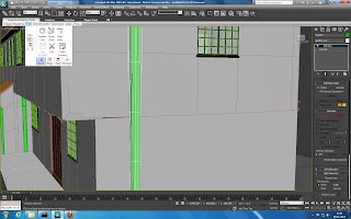
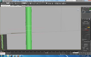
A new tool I learnt to use was the swift loop tool. This allows the user to create a new set of faces by selecting a line to split the original. The first step to doing this is to convert the shape into an editable poly.
To find the tool you can then move to the toolbar in the top left hand corner named, "graphic modelling tools" and then going to the "edit" sub-bar. This drops down into a new menu and the tool can be found in the right hand corner. You then loop the item and then create new vertex where necessary, creating new ploys.
This works well when changing whole shapes is required and the user wants to have a good flow of polys.
 |
| Selecting the Swift Loop tool |
 |
| Using the tool to create new vertex |
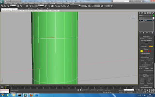 |
| The finished ajustment to the poly |
Friday 25 November 2011
Display Cabinet
To design the display cabinet I started with the legs. To do this I used the Pro Boolean tool. The way this works is by first creating two shapes. First the shape you want to cut into, and secondly the shape your going to use to cut the shape.
The next step is to move the second object into the 1st, covering the section you want to cut into. Then by selecting the first object and going onto the compound shape tab you can select the Pro Boolean tool.
After selecting Pro Boolean, the next step is to select the "Start picking" option and then select the second object (the cutting tool). This will then cut the shape into the first object.
This helped to create the wooden corners of the display table. The next step was to add a long cylinder to create the basic leg shape. Once this was done I moved on to create the basic shape for the display cabinet and added the lefs to the bottom.
To create this outa case I made a box shape, moved the vertexs to create the triangular shape and then used the inset and extrude tool to create the inside space. The next step was to create an inner layer that will be used to mimic the glass case.
The final step was to create the wooden top finish to go over the top of the glass case. This was done by making a copy of the box, cutting the top layer off and then extruding it out to give it depth. I then used the chamfer tool to round the edges and fit it to the display cabinet.
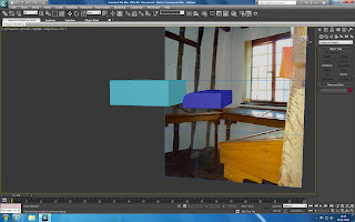 |
| Both objects |
The next step is to move the second object into the 1st, covering the section you want to cut into. Then by selecting the first object and going onto the compound shape tab you can select the Pro Boolean tool.
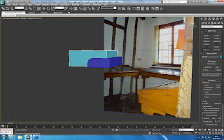 |
| Objects n overlapping |
After selecting Pro Boolean, the next step is to select the "Start picking" option and then select the second object (the cutting tool). This will then cut the shape into the first object.
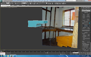 |
| Finished object |
 | ||
| Display cabinet outer case |
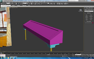 |
| Glass layer |
The final step was to create the wooden top finish to go over the top of the glass case. This was done by making a copy of the box, cutting the top layer off and then extruding it out to give it depth. I then used the chamfer tool to round the edges and fit it to the display cabinet.
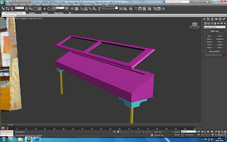 |
| Display cabinet lid |
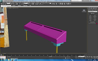 |
| Finished cabinet |
Subscribe to:
Posts (Atom)
